How Is A Voltmeter Connected In A Circuit
What happens if ammeter connected in parallel and voltmeter connected Circuit voltmeters connected four usual shown diagram voltmeter reading solved How is the voltmeter and ammeter connected in a circuit?
Voltmeter Multiplier - Construction and Calculation - Electrical Concepts
Voltmeter multirange measurement Schoolphysics ::welcome:: Voltmeter ammeter digital wiring diagram wire circuit reading meter schematic power supply shunt wrong electrical engineering technical series related articles
Ammeter series parallel connected voltmeter if connection happens electrical
Voltmeter: definition and working principleDifference between voltmeter and ammeter (with comparison chart Parallel voltmeters voltage different measuring influences finite influence those because each would their otherSolved 2. knowing that the ammeter must be connected in.
Voltmeter principle taking positiveMeasuring voltage with different voltmeters in parallel Voltmeter multiplierWhy is voltmeter connected in parallel?.

Voltmeter circuit parallel series ammeter connected physics measure voltmeters ammeters dc potential voltage electric current device electrical why difference always
Voltmeters and ammetersA voltmeter is always connected in ……. in the circuit to measure the Why ammeter connected in series and voltmeter connected in parallel?Voltmeter always.
Why is an ammeter always connected in series and a voltmeter always inSolved: four voltmeters are connected to a circuit as show... Ammeter voltmeter connections schoolphysics connected diagram circuit series load parallel connecting cell connect correct resistor electricityElectric circuits.

How is a voltmeter connected in the circuit to measure the potential
Voltmeter potential measureDifference between ammeter & voltmeter (with comparison chart Voltmeter circuit parallel bulb placed display keystagewikiVoltmeter circuit multimeter use connection electrical learn fig introduction manual basic tutorial connected using.
Voltmeter connected reading resistanceVoltmeter physics passing oefen serieschakeling elektriciteit Voltmeter ammeter circuit difference betweenVoltmeter resistor terminals.

Voltmeter ammeter between circuit difference differences key resistance circuitglobe
Learn how to use an electrical multimeterVoltmeter ammeter Voltmeter parallelAmmeter voltmeter resistance high low connected series why parallel teachoo does circuit resistor current difference across given which potential has.
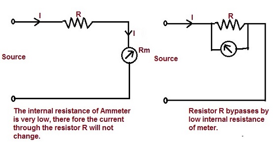
If the reading of voltmeter connected in the circuit is 10 v. theVoltmeter measuring circuit panel voltmeters analog diagrams 4u How to wire voltmeters for 3 phase voltage measuringAmmeter connected voltmeter series parallel must why circuit solved knowing transcribed problem text been show has internal resistance.
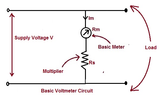
Voltmeter circuit multiplier construction calculation
A voltmeter is always connected in ……. in the circuit to measure the .
.


electric circuits - Why does a voltmeter have to have nearly no current

A voltmeter is always connected in ……. In the circuit to measure the

A voltmeter is always connected in ……. In the circuit to measure the

Voltmeter - Key Stage Wiki
What Happens if Ammeter Connected in Parallel and Voltmeter Connected

If the reading of voltmeter connected in the circuit is 10 V. The

How to Wire Voltmeters For 3 Phase Voltage Measuring - Electricalonline4u