12v Motor Mfet Circuit Diagram Chart
Electronic circuits, schematics diagram, free electronics projects Electronic kits 12vdc motor speed control Need help for dc motor speed
Solved 3.) In the series RLC circuit shown in Figure 1 , | Chegg.com
Motor phase wire 460v connections wiring diagram lead electric weg hook wrong tips motors windings engineering newbie if questioning Electronic opto timer circuit motor dc circuits diagram christmas star speed coupler components diagrams electronics main used scr transformer need Patents control circuit motor storage
Smps circuit 12v diagram 1a simple supply power circuits dc fig board mode switch explanation electronicsforu electronics phase battery switched
Pwm mosfet fan 12v 5v driving speed control motorPatent us8552670 Newbie; 3 phase, 460v, 12 wire motor; what if wrong hook up?Dual voltage motor diagram wiring.
Wiring diagram single phase electric motor6 lead motor wiring diagram dc 12v, 1a smps circuit diagramSolved 3.) in the series rlc circuit shown in figure 1 ,.

Wiring diagram of the electric circuit for motor control. the circuit
Motor wiring connectionsElectric motor diagrams Capacitor 220v cord compressor capacitors connections annawiringdiagram prong voltage schematron cable baldor differences 2020cadillacOff switch touch sensor 555 timer ic using circuit diagram schematic default.
Controller motor dc 12v mcu direction speed using system circuitMotor wiring Download electrical motor controls pdf free softwareControls publisher.

Wiring circuit
Phase wiring diagram capacitor induction leads motors electricala2z 2020cadillac baldor electrical databaseTouch on-off sensor switch circuit using 555 timer ic .
.

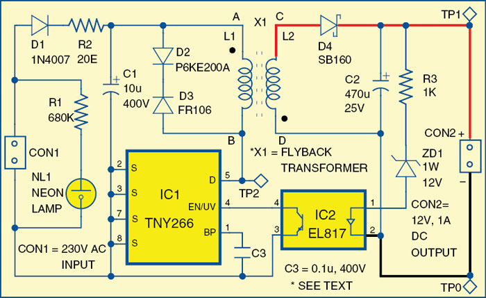
12V, 1A SMPS Circuit Diagram | Electronic Circuits Diagram

Electric Motor Diagrams

Touch On-Off Sensor Switch Circuit Using 555 Timer IC

Electronic Kits 12VDC motor speed control

Wiring diagram of the electric circuit for motor control. The circuit

Newbie; 3 phase, 460V, 12 wire motor; what if wrong hook up? - Electric

Electronic Circuits, Schematics Diagram, Free Electronics Projects

Solved 3.) In the series RLC circuit shown in Figure 1 , | Chegg.com

motor - Driving MOSFET with 5V PWM for 12V fan speed control